Bearing Capacity & Settlement
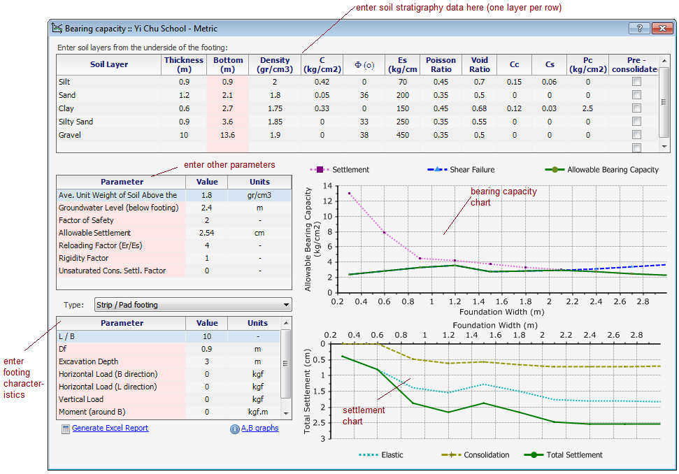
This module is used to calculate allowable bearing capacity of shallow foundations with simultaneously checking both shear failure and settlement. Each part of this page is explained below.
Note: Please read this article to see how PEYSANJ carries out bearing capacity analysis.
Project Information
From the top toolbar, select the Project tab, then click on Project button.
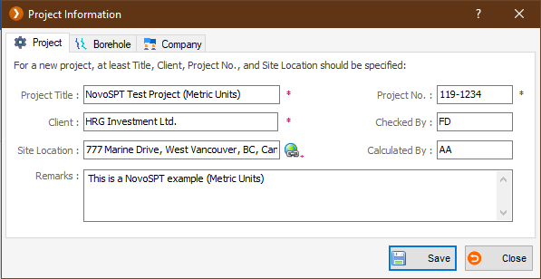
On this page, please enter project title, client name, project code, etc. This data will be shown on the reports.
Soil Layers Table
Your stratigraphy model may contain unlimited soil layers. Please specify the following parameters for each layer:
- Soil Layer: simple description for layer. This field is only for user's information and does not have any effect on bearing capacity analysis
- C: Coefficient of cohesion.
- Φ (deg): Internal angle of friction (between zero and 45 degrees).
- Es: Modulus of elasticity.
- v: Poisson ratio (between zero and 0.5).
- γ: Total unit weight.
- Z1: top depth of the layer.
- Z2: bottom depth of the layer. There should be no gap between layers, so Z1 for this layer should be same as Z2 for layer above. For the last layer use a very large number like 1000m to assure that stress bulb would not pass the bottom of your model.
- Su: Undrained shear strength. This parameter should only be entered when Φ=0; based on Hanson bearing capacity theory, when Φ=0 then Su will be considered for shear failure analysis.
- Cc , Cs: Consolidation compression and re-compression indexes. They should only be entered when you want the consolidation settlement to be calculated for this layer. If these parameters are entered but water level is below this layer, unsaturated consolidation settlement will be calculated for this layer (Suunsaturated=Susaturated*a where a is a factor less than one). You may specify 'a' in the "Analysis Parameters" frame.
- Pc: Pre-consolidation stress for consolidation settlement.
- eo: Void ratio.
- Pre-consolidated: Select this checkbox if the clay layer is pre-consolidated.
 To delete a soil layer, select the corresponding row and press SHIFT + DELETE on your keyboard.
 If there is bedrock in your subsurface model, enter only the soil layers; When program computes the stress bulb, no settlement will be calculated below the model.
 We recommended you save the data periodically to avoid data loss.
In this section, ground water level and wet unit weight for soil above the foundation level should be specified. Please notice that ground water level is measured from underneath the footing (always positive number).
Analysis Settings
This section contains the main parameters that are used for bearing capacity analysis:
- Allowable Settlement: this is usually one inch (25.4mm) for pad/strip footings.
- Er/Es: is the ratio of modulus of elasticity of re-loading (Er) to loading (Es) part. The best way to estimate the Er is to conduct a Plate Loading Test; at the beginning of the second cycle of a Plate Loading Test, the slope of the stress-deformation curve (Er) is much sharper than the normal slope of the curve (Es). PEYSANJ uses this Er/Es ratio to apply the stress history effect on the elastic settlement. For example, if your footing Df = 3 ft and γ=115 pcf then γ.Df=345 psf; So during elastic settlement analysis, PEYSANJ will use Er for stress range 0 to 345 psf and thereafter, Es will be used for estimation of settlement.
- Rigidity Factor (Ir): This factor is less than zero and depends on rigidity of the footing (usually 0.9 to 1). PEYSANJ applies this factor to the total settlement of the footing S=(Se+Sc)*Ir where Se and Sc are elastic and consolidation settlements, respectively.
- α Factor: this factor is used for calculation of un-saturated consolidation settlement. If a fine-grained layer is unsaturated (e.g. S=80%), then the actual consolidation settlement is a fraction of calculated saturated consolidation settlement.
- Safety Factor: this parameter is applied to the estimated ultimate shear failure of the soil present below the footing.
Foundation Size
- Shape: you may choose among "Pad/Strip", "Raft/Spread/Mat" and "Circular" foundations.
- Size Ratio (L/B): is used to specify the length to width ratio of the footing.
- Df : is the height of the soil around and above the footing (affects the shear failure).
- D : depth of placement of the foundation (usually depth of excavation).
- MB, ML: The bending moment applied on the footing.
- HB, HL: The horizontal forces applied to the footing.
- V : The vertical force applied on the footing.
 Note : For raft foundations, consider Df and D same as the excavation depth.
Calculating
Please press Calculate button on the top toolbar (Project tab) once the input parameters are entered.
Pad/Strip Footings Outputs
For this type of footings, two charts are presented:
Bearing Capacity Graph: Includes 3 curves; for all of them vertical axis is the allowable stress and horizontal axis is the foundation width (B); please note that, you have already entered L/B ratio so as B increases, the chart covers various foundation sizes:
- Shear Failure Curve (blue): Only encompasses the shear failure criteria for the model.
- Allowable Settlement Curve (purple): This curve shows the allowable stress, provided that the total settlement is around the allowable settlement already introduced by the user.
- Allowable Bearing Capacity Curve (green): This curve is the lower intersection of two above-mentioned curves and assures that on each point along the curve, both settlement and shear failures are within the allowable limits.
Settlement Graph: This includes 3 curves representing Immediate (elastic), Consolidation and Total settlements. Please be advised that these settlement values are calculated based on the resulting allowable bearing capacity calculated for each specific footing size. See how PEYSANJ conducts bearing capacity analysis.
Raft Foundation's Output
![]() For raft foundations since the footing size is considerable, shear failure is typically not governing the design, and restricting the settlement to allowable settlement will control the bearing capacity. Based on user-defined allowable settlement for the footing, the corresponding allowable stress is picked from the settlement plot and is shown on a box.
For raft foundations since the footing size is considerable, shear failure is typically not governing the design, and restricting the settlement to allowable settlement will control the bearing capacity. Based on user-defined allowable settlement for the footing, the corresponding allowable stress is picked from the settlement plot and is shown on a box.
Exporting the Results to Microsoft Excel
Click on the Excel tab in the bearing capacity page. This will generate an Excel file containing all Allowable bearing capacity and settlement values for various L/B ratios and different foundation widths (B). The width range and L/B ratios can be specified in the Option page.
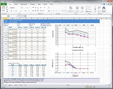
 To generate the Excel file, please click on "Export to Excel" button on Excel tab. This will take few minutes to prepare the file. Please be patient.
- When you prompt to open the Excel file, please select Yes. When Excel opens the file click on the tabs below the page to view the charts or calculation summary.
- You can easily copy and past all charts into your other Windows applications (such as Word). please click on top-left corner of charts and right-click. Then choose Copy from the popup menu. Now you just need to paste the chart into your destination program (such as Word).
Printing the Results
Press Print button from the toolbar to see the calculation details and the report.